Static Synchronous Compensator (STATCOM)
Overview
A STATic synchronous COMpensator (STATCOM) is a fast-acting device capable of providing or absorbing reactive current and thereby regulating the voltage at the point of connection to a power grid. It is categorised under flexible alternating current transmission system (FACTS) devices. The technology is based on voltage source converters (VSCs) with semiconductor valves in a modular multi-level configuration.
The dynamic reactive current output range is almost symmetrical (during normal disturbed network conditions). However, non-symmetrical designs are possible by introducing mechanically or thyristor switched shunt elements with unified control systems to cover most conventional applications.
Technology Types
A typical STATCOM configuration consists of multi-level VSCs based on Insulated Gate Bipolar Transistors (IGBTs), phase reactors and a step-up transformer, and it is shunt-connected to the grid. The reactive current is provided or absorbed by producing a controlled internal voltage waveform. Most STATCOMs available in the market today operate as Grid-Following-Control and require a grid voltage reference to operate (with a defined level of grid strength). However, new products with Grid-Forming-Control (GFC) and storage appear on the market.
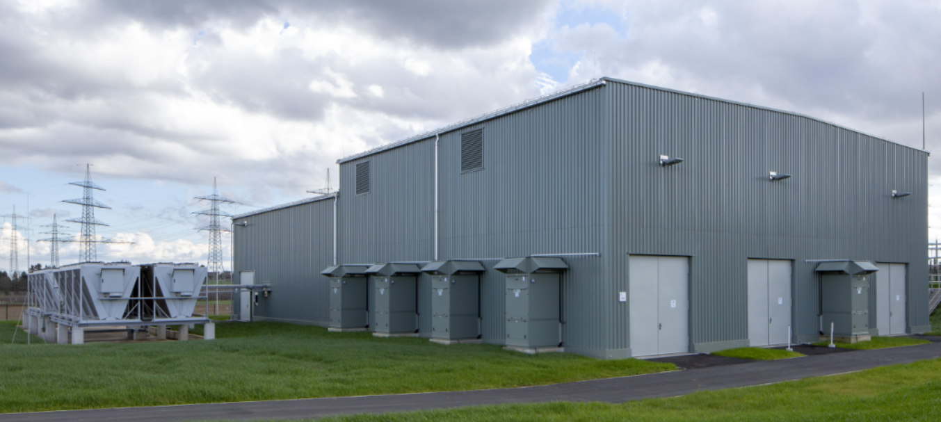
![Figure: Inside view of the static synchronous compensator hall. Source Amprion [1].](/assets/graphics/uploads/technopedia/statcom2.jpg)
Benefits
The benefits of STATCOMs are listed below:
- The major characteristics of STATCOM are fast response time (less than 2 cycles), high operational flexibility, superior under-voltage performance, excellent over-voltage performance, a configuration with typically no harmonics filters, low space requirements compare to Static Var Compensators (SVCs), high availability and a hybrid design to cater to non-symmetric grid requirements and others.
- The STATCOM design and fast response makes the technology very convenient for maintaining voltage during network faults (STATCOMs are, in fact, capable of providing fast fault current injection limited to the rated current) and for enhancing short term voltage stability thanks to the technology grid forming capability. In addition, STATCOMs can provide power factor correction, reactive power control, the damping of low-frequency power oscillations (usually by means of reactive power modulation), active harmonic filtering, flicker mitigation and power quality improvements.
- STATCOMs under development will also be capable of providing instantaneous active power to the grid.
Current Enablers
The list below describes some enablers to be able to install and use STATCOMs:
- Availability of the power electronics;
- Manufacturer resources for the implementation of the new abilities as GFC with storage; and
- Alignment of the basic requirements for STATCOMs and development towards a few standard equipment families.
R&D Needs
Several R&D activities, listed below, can contribute to further improving the technology:
- The development of STATCOM with GFC to provide more ancillary grid services, such as inherent current response to changes in grid voltage or / and amplitude;
- The development of STATCOM with GFC and energy storage (e.g. batteries or supercapacitors) for the provision of instantaneous power reserve (inertia) support;
- Studies on harmonic interactions between other active components such as High Voltage Direct Current (HVDC), neighbouring STATCOM and conventional components such asynchronous condensers to enhance the coordinated use of multiple devices and area voltage regulation, including instability detection technologies;
- Improvements of dynamic performance, stable steady-state and dynamic behaviour, reactive power output, cost, facility footprint and noise; and
- Demonstrations of mobile and scalable STATCOMS, which can be moved from one location to another.
The technology is in line with milestone “Development of high power innovative transmission components” under Mission 1 of the ENTSO-E RDI Roadmap 2024-2034.
TSO Applications
Examples
| Location: Amprion, Germany [2] | Year: 2023 |
|---|---|
| Description: Implementation of the first STATCOM with GFM capability in the Amprion Grid. | |
| Design: +/- 300 Mvar, 420 kV, GFM. | |
| Results: In operation. | |
| Location: Eles, Slovenia [3] | Year: 2022 |
|---|---|
| Description: Stationary compensation device with a SVC/STATCOM technology of +/- 150 Mvar at the Beričevo substation. This is part of an optimal combination of various high-tech advanced devices for the compensation of reactive power and voltage regulation through a cross-border partnership between Slovenia and Croatia. | |
| Design: +/- 150 Mvar. | |
| Results: In operation. | |
| Location: National Grid, UK [4] | Year: 2020 |
|---|---|
| Description: Dynamic Reactive Compensator (DRC) project, the largest STATCOM scheme in Europe. It delivers a 975-MVAR power range. It is deployed and coordinated over 3 separate substations along the transmission network in southeast U.K. | |
| Design: 975 Mvar. | |
| Results: In operation. | |
| Location: Borken, Germany [5] | Year: 2018 |
|---|---|
| Description: The first German hybrid STATCOM facility has been in operation since 2018 to dynamically support the voltage and enhance the power quality at the 380 kV level. | |
| Design: Hybrid construction of the reactive power compensation system, with two STATCOM branches and a Mechanical Switched Capacitor with Damping Network (MSCDN) providing reactive power compensation within the range of -250 Mvar to +400 Mvar. The MSCDN is used to provide the capacitive base load. | |
| Results: Provides wide reactive control range and enhances power quality. | |
Technology Readiness Level The TRL has been assigned to reflect the European state of the art for TSOs, following the guidelines available here.
- TRL 9 for conventional STATCOM at high voltage and extra high voltage.
- TRL 6 for GFC at high voltage and extra high voltage.
- TRL 5 for GFC and storage at high voltage and extra high voltage.
References and further reading
Amprion.“New technologies”
Amprion. “Amprion und Hitachi Energy nehmen STATCOM in Betrieb.”
Sincro grid. “STATCOM put into operation.”
Power Grid International. “UK’s National Grid gets first-of-its-kind STATCOM scheme.”